GE / IP FANUC Series 90/30 In Stock

Analog PLCs: Voltage vs Current
Programable logic controllers (PLC) are devices known to be completely digital, and, usually, digital devices are very easy to understand in the electrical side of things, they work with binary language, 1 and 0, true and false, reference voltage and ground, and this is true even today. But then, how do they have the capability to harness analog signals?
Well, at the beginning, PLCs just weren’t capable of such a thing, but with the continuous advance in technology, they have become powerful enough to support measurement of analog signals. Even though PLCs are digital devices at heart, developers make use of analog to digital (ADC) and digital to analog (DAC) converters to be able to translate between both states.
Having said this, some people struggle with analog signals at the moment of programming and wiring the analog inputs and outputs, due to the electrical theory, math and memory management that goes in the middle of analog I/O theory. Not only that, but each PLC also has its own configuration and electrical characteristics which can completely change the way every analog application must be handled.
Voltage and Current
To be able to have the best understanding on the subject, it is necessary to come back to the basics because sometimes even seasoned professionals don’t have the concepts of current and voltage completely clear. It is often difficult to visualize the fundamental workings of electricity because, obviously, visual representation is impossible. Most people use the analogy of water flow, but even that is not 100% accurate to how electricity works, so here we will provide a quick refresher.
Voltage
Voltage is described in many different ways, some call it electrical pressure, others tension, and others, maybe the most used term, potential difference. But what is voltage? There are two principal definitions for it, first, the pressure that pushes charged electrons from one point to another, and second, the difference in potential energy between two points. This already should give the idea that the voltage is always measured between two points.
Current
Current has a much simpler definition. An ampere, the unit used to represent current, expresses the number of electrons passing through a certain point in a given unit of time. To be more specific, 1 ampere is equal to 6.24×10¹⁸ electrons passing through a point in the circuit in 1 second. Its simple explanation is ironic considering how tricky it can be measuring and controlling the current. For instance, to be able to measure current the instrument must be placed in series, this means cutting off the circuit, and placing the instrument in the middle of the point that needs to be measured.
Both definitions show a clear difference between them: the voltage of a load is measured by placing the input parallel to a load, and the current is measured by placing the input in series to the load. This shows that the voltage is very easy and straightforward to measure, on the other hand, the current requires a bit more of setup for that, and that will be explained below.
Analog Signals
As was mentioned before, PLCs are digital devices, that means that everything stored in them are represented as binary values (0 and 1) which is great for digital signals, but it is possible to store analog values with “words”, which are arrangements of two bytes or eight binary numbers. Each PLC analog I/O card has its own characteristics, which will show how it will display the analog signals, these characteristics are:
- Resolution: the number of bits available to save the value of the analog signal.
- Range: the voltage/current range supported by the analog I/O.
- Over-range: an extra layer over the normal range.
- Under-range: an extra layer under the normal range.
With all of these characteristics, we are able to calculate the amount of current that the analog I/O card is able to read for each increment of 1 in the set of words, it is worth noting the over-range and under-range, which work as a way to monitor the possible peaks and drops that an analog may suffer in real working conditions, this would help the users to find any problem in the system.
Analog Inputs
The analog signals can come from different types of sensors, which, at the same time, have their signals transformed by a transmitter, which is the device in charge of transforming the physical signal to an electric signal, although it can be used as well to transform any electrical signal to one suitable for the analog I/O card. There are some PLC products that are able to connect certain sensors directly to the I/O, but most of the time this is not the case.
Wiring for Voltage Analog Inputs
As it was explained before, voltage is always measured in parallel to the load that we need to measure, so it just needs a simple 2 wire connection, an AIN which goes to the node that needs to be measured, and an AGND which goes to a reference point for the voltage that is going to be measured, this is usually ground, but sometimes the user might need differential measurements which will depend on the characteristics of the hardware.

Wiring for Current Analog Inputs
This is where it gets a bit more problematic, a current analog input doesn’t even measure current directly, it measures the voltage of a known shunt resistor, then the current is calculated from the voltage and resistance values. This is achieved by connecting both sides of this shunt resistor to a closed loop circuit, which will have the controlled current running through it. The wiring for current analog inputs is classified by three:
2-wire Analog Input:
This, at the same times, have two variations, the first using the internal power supply from the analog I/O module, which would only need to have connected the supply and analog input cable to the transmitter, and the second using an external power supply, which would need a connection between the analog and source grounds, the output of the source going to the transmitter, and then the other side of the transmitter going to the analog input.

3-wire Analog Input:
The 2-wire connection has a small problem, a closed loop means that the transmitter acts as a load, and if it consumes more current than the lower side of the range, it can mess with the readings, this is where the 3-wire connection comes in. This connection uses the external power supply to power the transmitter in a secondary loop, so the principal current loop is only used for the analog current measurement.

4-wire Analog Input:
The 4-wire connection uses a similar approach to that of the 3-wire connection, but it adds the advantage of not having a common ground between the power supply and the analog I/O module, so it completely separates both loops, avoiding any disturbance in the power supply over the analog current loop.

Analog Outputs
In the output side things are as straightforward as it can be, same principles apply, parallel design for voltage, series design for current, but there are still a couple of differences.
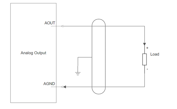
Wiring for Voltage Analog Output
In the case of the output, the wiring is the same to that on the input, it just needs to apply the analog voltage in parallel to the load that is going to be controlled. One variation that is worth to have in mind, is the addition of two more terminals to be able to compensate line impedance, in this case the two extra wires are connected in parallel together with the principal terminals. For precaution, the users must be careful to know the load impedance, which in the case of being too low, can damage the analog module by producing a short-circuit.
Wiring for Current Analog Output
In the case of the output for analog currents, the connection is a simple 2-wire connection, with the analog output going through the load to the analog I/O module analog ground. Contrary to the voltage, the current analog output has to deal with a maximum load impedance, since, in the case that it is too large, the analog output won’t be able to pass current through that loop.

Analog Signals in the PLC
Analog signals are incredibly useful, they provide the opportunity to read sensors that have much more information than just on or off, and to control devices in an incremental and continuous manner, for instance we can measure temperature with the help of a thermocouple, which should be connected to a transmitter that would transform the small voltage produced to a common analog signal for the PLC.
As for the usually range used, the 4-20 mA current range is the industry standard for any analog current control, it is very useful since it has some space for an under-voltage range, and, since it has been used for so long, there is a tone of support over the use of that range, not only in PLCs but in other modular developed controllers, guaranteeing huge compatibility.
At the end of the day, the most important thing about analog signals is that the terminals used must meet the electrical characteristics of the sensors and devices connected to them, it is important for anyone trying to install a new instrument, sensor or device to the analog I/O module of their PLC, to read the manuals, these will have all the necessary information and support that anyone would need for a successful installation.
Tags: analog, analog plc, Analog Signal, Current vs Voltage, Electricity
This entry was posted on January 29th, 2021 and is filed under Automation, Education, Electrical, General, PLC, Technology. Both comments and pings are currently closed.
PDF Supply sells used surplus products. PDF Supply is not an authorized distributor, affiliate, or representative for the brands we carry. Products sold by PDF Supply come with PDF Supply’s 1-year, 2-year, or 3-year warranty and do not come with the original manufacturer’s warranty. Designated trademarks, brand names and brands appearing herein are the property of their respective owners. This website is not sanctioned or approved by any manufacturer or tradename listed.
Rockwell Disclaimer: The product is used surplus. PDF Supply is not an authorized surplus dealer or affiliate for the Manufacturer of this product. The product may have older date codes or be an older series than that available direct from the factory or authorized dealers. Because PDF Supply is not an authorized distributor of this product, the Original Manufacturer’s warranty does not apply. While many Allen-Bradley PLC products will have firmware already installed, PDF Supply makes no representation as to whether a PLC product will or will not have firmware and, if it does have firmware, whether the firmware is the revision level that you need for your application. PDF Supply also makes no representations as to your ability or right to download or otherwise obtain firmware for the product from Rockwell, its distributors, or any other source. PDF Supply also makes no representations as to your right to install any such firmware on the product. PDF Supply will not obtain or supply firmware on your behalf. It is your obligation to comply with the terms of any End-User License Agreement or similar document related to obtaining or installing firmware.