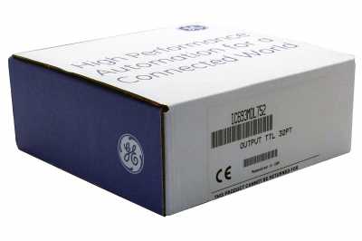
GE / IP FANUC Series 90/30 In Stock

IC693MDL752
SKU 2171209 UPC 0553640565557
All product names, trademarks, brands and logos used on this site are the property of their respective owners. PDF Supply is not an authorized distributor, reseller or representative of the products featured on this website. The depiction, description or sale of products featuring these names, trademarks, brands and logos is for identification purposes only and is not intended to in indicate any affiliation with or authorization by any rights holder.
PDF Supply is NOT an authorized distributor for this manufacturer and therefore the manufacturer’s warranty does not apply. Product comes with PDF Supply's 1-year, 2-year, or 3-year warranty.
Other Available Revisions for the IC693MDL752 IC693MDL752AIC693MDL752BIC693MDL752CIC693MDL752-CAIC693MDL752DIC693MDL752EIC693MDL752FIC693MDL752GIC693MDL752HIC693MDL752JIC693MDL752KIC693MDL752-LTIC693MDL752-RR
Common misspellings:
- 1C693MDL752
- IC693MD1752
- IC693MDL752
Product Description
The 5/24-volt DC (TTL) Negative Logic Output module, IC693MDL752, has 32 negative logic or sinking type output points (active low) and uses 32 bits of discrete %Q output data. The outputs are arranged in four separate groups (labeled A to D), each group comprised of eight outputs each (numbered 1 to 8) with each group having its unique common. It can be installed in any Series 90-30 Programmable Logic Controller (PLC) system having a 5 or 10- I/O slot baseplate. Each group common has user I/O connectors which carry two pins. Each pin on these connectors has a current handling capacity of 3 amperes. Making connections to both pins is recommended when connecting the common, but required for applications requiring high current such as between 3 and 4 amperes.
The IC693MDL752 operates in two modes: Transistor-Transistor Logic (TTL) and 12/24V modes. In the TTL mode, each output can switch user loads across +5 VDC. In 12/24V mode, user loads can be switched in the range of +12 to -24 VDC. Also, output points, in each mode (TTL and 12/24V), can sink a maximum current of 25 mA and 0.5A per point respectively. Each output group in the module (A to D) can be utilized in the operating mode that is appropriate for the load requirements of a specific task or application. Group A can be applied to TTL load tasks and Group B to 12 VDC loads, while the Groups C and D can be applied to 24 VDC load tasks. However, when mixing modes (TTL and inductive-type loads), as in this regard, it is important to take cognizance of electrical noise and its effects.
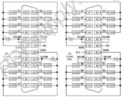
User load devices are connected to the module through two male 24-pin connectors that are located on the front of the module. The connectors on the right interfaces with groups A and B output points while those on the left interfaces with groups C and D output points. Optocouplers on the module provide backplane isolation between the field side and logic side. The module also has LED indicators, labeled correspondingly to each output, at the top of the module which indicates the active (ON) or inactive (OFF) status of each output point. There is no reporting of special fault or alarm diagnostics.
Each output point has an internal pull-up resistor. When the output point's field-effect transistor (FET) is off, the resistor aims at providing a high logic level for TTL tasks. It does this by pulling up the output to the positive side of the user power input, which, for TTL tasks, is typically +5V. Stopping the CPU forces all 32 output points off and the user must provide power to supply current to the loads. A minimum amount of the user-supplied power is used by the module to provide gate drive to output devices.
Technical Specifications
| Rated Voltage: | 5 and 12 thru 24 volts DC |
| # of Outputs: | 32 |
| Freq: | n/a |
| Output Current: | 25 mA per point (TTL mode) |
| Output Voltage Range: | 4.75 to 5.25 volts DC (TTL mode) |
| DC Power: | Yes |
Technical Information
Specifications
|
Rated Voltage |
5, and 12 through 24 volts DC, negative logic (active low) 4.75 to 5.25 volts DC (TTL mode) 10.2 to 28.8 volts DC (12/24V mode) 32 (four groups of eight outputs each) 1500 volts between field side and logic side 250 volts between groups 25 mA per point (maximum in TTL mode) 0.5 amps per point (maximum in 12/24V mode); with 4 amps maximum per group and 3 amps maximum per group common pin
4.6 amps for 10 ms 0.4 volts DC (maximum in TTL mode) 0.24 volts DC (maximum in 12/24V mode) 0.1 mA maximum 0.5 ms maximum 0.5 ms maximum 260 mA (maximum) from 5 volt bus on backplane; (13 mA + 3 mA/point ON + 4.7 mA/LED) 12 mA (maximum) per group from user supply @ 5VDC and all eight outputs in group ON 25 mA (maximum) per group from user supply @ 12 VDC and all eight outputs in group ON 44 mA (maximum) per group from user supply @ 24 VDC and all eight outputs in group ON |
|
Output Voltage Range |
|
|
Outputs per Module |
|
|
Isolation |
|
|
Output Current |
|
|
Output Characteristics |
|
|
Inrush Current |
|
|
On-state (active low) |
|
|
Voltage Drop |
|
|
Off-state Leakage Current |
|
|
On Response Time |
|
|
Off Response Time |
|
|
Internal Power Consumption |
Troubleshooting
Troubleshooting IC693MDL752
Troubleshooting information is available on IC693MDL752’s website page; it also includes a datasheet user-manual and a wiring diagram.
Repair your IC693MDL752
PDF Supply can repair your IC693MDL752 in 3-5 business days. And PDF Supply stands by all of its repairs with a 1 year customer satisfaction warranty.
Customer Questions and Answers
- Question: What is an IC693MDL752? Answer: The IC693MDL752 is a 5/24 volt DC (TTL) Negative Logic Output module for the GE Fanuc Series 90-30. This module provides 32 discrete outputs which are arranged in 4 isolated groups of 8. Each group has its own common.
- Question: What kind of outputs does this module have? Answer: The IC693MDL752's outputs are negative logic or sinking type outputs.
- Question: How many modes of operation does IC693MDL752 have? Answer: It has 2 modes of operation.
- Question: What are those modes of operation? Answer:
- TTL mode- In this mode the outputs can switch user loads across +5 VDC and are capable of sinking a maximum current of 25 mA per point.
- 12/24 mode- In this mode the outputs can switch user loads over the range of +12 through -24 VDC and are capable of sinking a maximum current of 0.5A per point.
- Question: As what type can this module be configured? Answer: The configuration of IC693MDL752 can be as a 32 point output type and it uses 32 bits of discrete output data.
- Question: What is the rated voltage? Answer: 5 and 12 through 24 volts DC, negative logic (active low)
- Question: What is the output voltage range? Answer: 4.75 to 5.25 volts DC (TTL mode)
- 10.2 to 28.8 volts DC (12/24V mode)
- Question: What is my next step if my IC693MDL752 is not working? Answer: If your IC693MDL752 is not working properly, then your product may need repair.
For more information on the IC693MDL752 DC (TTL) Negative Logic Output Module of the GE 90-30 Series, please see the Datasheet Manual.
Common related search terms: BuyDatasheet, Emerson, Manual, Price, Repair, Specification, Troubleshoot, Wiring,


