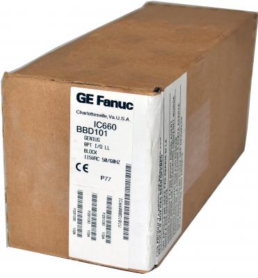
GE / IP FANUC Series 90/30 In Stock

IC660BBD101
SKU 2176160 UPC 0313814319979
All product names, trademarks, brands and logos used on this site are the property of their respective owners. PDF Supply is not an authorized distributor, reseller or representative of the products featured on this website. The depiction, description or sale of products featuring these names, trademarks, brands and logos is for identification purposes only and is not intended to in indicate any affiliation with or authorization by any rights holder.
PDF Supply is NOT an authorized distributor for this manufacturer and therefore the manufacturer’s warranty does not apply. Product comes with PDF Supply's 1-year, 2-year, or 3-year warranty.
Other Available Revisions for the IC660BBD101 IC660BBD101AIC660BBD101BIC660BBD101CIC660BBD101-CAIC660BBD101DIC660BBD101EIC660BBD101FIC660BBD101HIC660BBD101KIC660BBD101LIC660BBD101MIC660BBD101NIC660BBD101PIC660BBD101QIC660BBD101RIC660BBD101-RRIC660BBD101SIC660BBD101TIC660BBD101UIC660BBD101VIC660BBD101-V1
Common misspellings:
- 1C660BBD101
- IC66oBBD101
- IC6608BD101
- IC660B8D101
- IC660BBDl01
- IC660BBD1o1
- IC660BBD10l
- IC660BBD101
Technical Specifications for IC660BBD101
| Manufacturer | GE Fanuc |
|---|---|
| Series | Genius I/O |
| Part Number | IC660BBD101 |
| Product Type | I/O Block |
| Voltage Rating | 115 Volts AC |
| Channels | 8 |
| Input Processing Time | 2 milliseconds plus filter |
| Selectable Filter Delay | 10 to 100 milliseconds |
| Maximum Inrush Current at up to 2 Cycles | 25 Amps |
| Operating Temperature | 0-60 degrees Celsius |
Product Description
IC660BBD101 is a GE Fanuc Low Leakage Input/Output Block that comes with eight discrete points/circuits and delivers 115 Volts AC. The input, as well the as operating voltage range, is between 93-132 Volts AC with a load current of 2 Amps. Each of its eight circuits can be configured for either input or output. The I/O block links multiple discrete sensors/actuators and a communication bus. The block can accommodate high input impedance. A fuse shuts down output current in the circuit if it goes beyond 30 Amps or 20 Amps for every two cycles. The circuit can later be restored by issuing a command from the CPU or a handheld monitor.
The I/O block comes with features such as input filters with selectable filter times ranging from 10ms -100ms, module control for bus switching, output feedback for voltage monitoring, pulse testing for output points, and defaults for output power-up.
LED indicators on the I/O block blink to alert the user to errors or faults such as faulty cabling, incorrect baud rate, and improper grounding among others. There is a dedicated LED for each circuit. For an output circuit, an LED, which in ON indicates that a specific circuit has complied with the command issued by the CPU. For an input circuit, however, an ON LED shows that a specific terminal has reached the threshold voltage. Error messages are generated on the handheld monitor, which helps the user attend to the fault promptly and efficiently.
The IC660BBD101 I/O block weighs 4lbs and works with model IC660HHM501 of the handheld monitor and IC693BEM331 bus controller model.
Technical Specifications
| Rated Voltage: | 115 volt AC |
| # of Points: | 8 |
| Input Range: | 93-132 VAC |
| Load Current: | 2 Amps |
| Operating Voltage: | 93-132 VAC |
| Points per Common: | One group of 8 |
Any disabled circuit on the IC660BBD101 I/O block can be enabled by sending the appropriate command from a hand-held monitor or from the system CPU. The features of the IC660BBD101 module include output pulse testing, output feedback, 10 to 100 milliseconds configurable input filter time, and Bus switching module control. The control power for the IC660BBD101 module is derived from the I/O device voltages wired to the I/O channels. Specifications for channels configured as inputs include 2 milliseconds (plus filter) of input processing time, 60 Volts RMS of minimum off-state voltage, and 1.5 milliamps of maximum off-state current. The specifications for channels configured as outputs include 2 Amps RMS of steady state current, 25 Amps of maximum inrush current, and 15 Amps of maximum block output current at 35 degrees Celsius.
Technical Information
Specifications
|
Blocktype: CatalogNumbers: Block: TerminalAssemblyonly: ElectronicsAssemblyonly: |
8 circuit combination input and output
IC660BBD101 IC660TSD100 IC660EBD101 |
|
Size (height x width x depth): Weight: LED’s (I/O block): LED’s (each circuit): Block to Block Isolation: HeatDissipation: |
8.83” (22.44cm) x 3.50” (8.89cm) x 3.94” (10.00cm) 4 lbs. (1.8 kg) UnitOK,I / OEnabled On logic side of switch 1500 V 16W maximum with 8 inputs 43.5W maximum with 8 outputs on at 2 amps. |
|
Standbypower (all inputs and outputs off): Operatingvoltage(singlesource): Frequency: Power supplydropouttime: |
8.5 Watts 93–132 VAC 47–63 Hz 1 cycle (16.7mS at 60Hz, 20mS at 50Hz) |
|
InputCharacteristics: Non–tristate input, OFF state: Minimum voltage across input device (IN to H) Maximum leakage through input device Non–tristate input, ON state: Maximum voltage across input device (IN to H) Maximum switch current threshold Tristate input, OFF state: Acceptable voltage across input device (IN to H) Tristate input, ON state: Maximum voltage across input device (IN to H) Input load network: Resistor to N Capacitor to H Input processing time (typical) Selectable input filter times Inputdiagnostics |
60 VRMS |
|
1.5 mA |
|
|
20 VRMS |
|
|
6 mA RMS |
|
|
16 VRMS–40 VRMS |
|
|
4 VRMS |
|
|
13K ohms |
|
|
.10 ïf |
|
|
2mS + filter |
|
|
10 to 100mS in 10mS increments |
|
|
Open Wire, Overtemperature, Failed Switch |
|
|
OutputCharacteristics: Circuit output current (steady state) Maximum inrush current up to 2 cycles Maximum inrush current 2–6 cycles Maximum block output current Output Leakage @ 115 VAC: Current at 0 volt output (OUT to N) Voltage at open output (OUT to N) Output switch (OFF to ON / ON to OFF) Maximumswitching frequency Turn–on delay (maximum) Voltage drop (at 2 amps) Voltage drop (at 30 amps inrush) Recommended min. load, resistive (No Load disabled): Recommended min. load, inductive (No Load dis- abled): No Load enabled threshold Fusing Outputdiagnostics |
2 amps RMS |
|
25 amps peak |
|
|
14 amps peak |
|
|
15 amps at 35C, 7.5 amps at 60C |
|
|
< 7mA |
|
|
65 volts |
|
|
Zerocrossing |
|
|
Once per second (high inrush currents) |
|
|
0.5 Hz + 1mS |
|
|
2.5 volts |
|
|
10 volts |
|
|
25mA |
|
|
40mA |
|
|
50mA |
|
|
Internal electronic short circuit trip. 100ms long time trip |
|
|
Short Circuit, Overload, No Load, Failed Switch, Overtemperature |
|
|
Environmental: Operating Temperature Storage Temperature Humidity Vibration |
0 to +60 C (32 to +140 F) |
|
–40 to +100 C (–40 to +212 F) |
|
|
5% to 95% (non–condensing) |
|
|
5–10 Hz 0.2” (5.08mm) displacement, 10–200 Hz at 1G |
Troubleshooting
Troubleshooting IC660BBD101
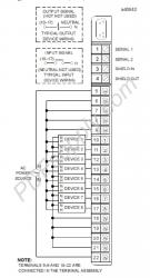
Troubleshooting information is available on IC660BBD101's website page; it also includes a datasheet, a user manual, and a wiring diagram.
Repair your IC660BBD101
PDF Supply can repair your IC660BBD101 in 3-5 business days. And PDF Supply stands by all of its repairs with a 1 year customer satisfaction warranty.
Undocumented Double Blink Code
Description: Excessive Genius bus errors can be show in many ways; for example, blinking or extinguished "Channel 1 OK" LED or erratic "I/O Enabled" LED. Additionally, a blink code that flashes "Unit OK" twice and "I/O Enabled" twice can mean excessive genius bus errors.
Resolution: Look for any errors (Baud rate mismatches, cabling problems, or poor grounding practices) and fix them.
Grounding and Noise Suppression
Description: The RTD common mode voltage is usually floating, with the RTN signals of each pair connected internally within the block. This any grounding or noise suppression should be ddone at the block on this line.
Resolution: Grounding RTN will eliminate noise spikes but may introduce DC errors in the readings. Bypassing with a MOV maintains the AC isolation but will bypass high voltage spikes. The SHLD terminal is chassis ground. Any commonly available 120 VAC MOV should be acceptable.
Customer Questions and Answers
- Question: What is an IC660BBD101? Answer: The IC660BBD101 is a 115 volt AC, 8-Point I/O Discrete Block of the GE Fanuc Genius I/O Series.
- Question: What will I need to test this block? Answer: You will need an IC660HHM501 Hand Held Monitor (this should be plugged into your IC660BBD101). You will need an IC693BEM331 bus controller (this should be plugged in through your serial one, two, and the shield). You will need a power cord (115 volt AC) and a raw probe (1 wire on one end and a probe on the other end). Finally, you can use a mechanics drop light as an easy way to test whether this block is working (so, if the light lights up when you touch the probe of the hot lead from the light to the inputs). To test the block through Proficy Machine Edition, you will also need a slot rack, a power supply, and a CPU.
- Question: Are there any recommendations when testing IC660BBD101? Answer: Yes, it is recommended you put a piece of electrical tape over your neutral leads so that you do not accidentally short-out anything.
- Question: Can I use the HHM for configuration of IC660BBD101? Answer: Yes, you can. Please see our YouTube video that is on IC660BBD101's website page on how to do that.
- Question: What indicates a good working block? Answer: If you are able to program it, if your serial communication is working (serial one, serial two through the Proficy Machine Edition and through the Genius bus controller), if the HHM is working while it's plugged in and is responding, and if all of your inputs and all of your outputs are working then this is a good working block.
- Question: How do I know if my IC660BBD101 needs repairing or replacing? Answer: If any of the above mentioned factors are not working, then your product may need repair.
For more information on the IC660BBD101 8-Circuit Grouped I/O Block of the GE Fanuc Genius I/O Series, please see the Datasheet User-Manual.
The final letter in the part number (ex. IC660BBD101K) indicates the revision. Revision K and later use the newer style electronic housing and therefore need the newer style plastic door and may indicate some compatibility issues with the terminal strip.
Common related search terms: ConfigurationDatasheet, Emerson, Manual, PDF, PLC, Price, Repair, Specification, Troubleshoot, User-Manual, Wiring,


