GE / IP FANUC Series 90/30 In Stock

GE Fanuc Versamax Troubleshooting
-
Troubleshooting Guide For VersaMax PLC and I/O Modules

Troubleshooting Guide for VersaMax PLC and I/O Modules.
The VersaMax family of products provides universally-distributed I/O that spans PLC and PC-based architectures. Designed for industrial and commercial automation, VersaMax I/O provides a common, flexible I/O structure for local and remote control applications. The VersaMax PLC provides big-PLC power with a full range of I/O and option modules. VersaMax I/O Stations with Network Interface Modules make it possible to add the flexibility of VersaMax I/O to other types of networks. VersaMax meets UL, CUL, CE, Class1 Zone 2 and Class I Division 2 requirements.
As a scaleable automation solution, VersaMax I/O combines compactness and modularity for greater ease of use. The 70-mm depth and small footprint of VersaMax I/O enables easy, convenient mounting as well as space- saving benefits. Modules can accommodate up to 32 points of I/O each. (VersaMax® PLC User’s Manual, 2006)
Below is a list of abbreviations we think you should know before continuing:
- CPU: Central Processing Unit
- DI: Digital Input Module
- DO: Digital Output Module
- ERM: Expansion Receiver Module
- GEIP: GE Intelligent Platforms/li>
- I/O: Input / Output
- LED: Light Emitting Diode
- NIU: Network Interface Unit
- OEM: Original Equipment Manufacturer
- PSU: Power Supply Unit
- PLC: Programmable Logic Controller
- RAM: Random Access Memory
- TB: Terminal Block
-
Section 1.1 – Power Supply Removal

Troubleshooting Guide for VersaMax PLC and I/O Modules.
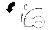
- Switch off the external power source to the power supply module.
- Turn the latch to the unlocked position.
- Press in the tabs on the lower edge of the power supply.
- Pull the power supply straight off (VersaMax® Modules, Power Supplies, and Carriers, 2003).
-
Section 1.2 – Power Supply Installation

Troubleshooting Guide for VersaMax PLC and I/O Modules.
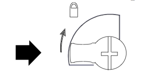
- The latch on the power supply must be in the unlocked position.
- Align the connectors, tab, and latch post on the power supply to be parallel with the CPU, NIU, ERM, or carrier.
- Press the power supply module down firmly, until the two tabs on the bottom of the power supply click into place. Be sure the tabs are fully inserted in the holes in bottom edge of the CPU, NIU, ERM, or booster carrier (VersaMax® Modules, Power Supplies, and Carriers, 2003).
- Turn the latch to the locked position to secure the power supply in place (VersaMax® Modules, Power Supplies, and Carriers, 2003).
-
Section 2 – Central Processing Unit (CPU)
Troubleshooting Guide for VersaMax PLC and I/O Modules.
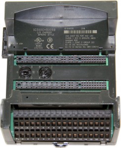
VersaMax® PLC CPUs IC200CPU001, CPU002, and CPU005 provide powerful PLC functionality in a small, versatile system. They are designed to serve as the system controller for up to 64 modules with up to 2048 I/O points. Two serial ports provide RS-232 and RS-485 interfaces for SNP slave and RTU slave communications (VersaMax® PLC User’s Manual, 2006).
-
Section 2.1 – Run/Stop Switch

Troubleshooting Guide for VersaMax PLC and I/O Modules.
The CPU module has a convenient switch that can be used to place the PLC in Stop or Run mode. The same switch can also be used to block accidental writing to CPU memory and forcing or overriding discrete data. Use of this feature is configurable.
The default configuration enables Run/Stop mode selection and disables memory protection (VersaMax® PLC User’s Manual, 2006).
-
Section 2.2 – LED Diagnostics
Troubleshooting Guide for VersaMax PLC and I/O Modules.
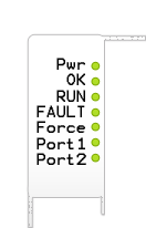
Power On when the CPU is receiving 5V power from the power supply. Does not indicate the status of the 3.3V power output. OK ON indicates the CPU has passed its powerup diagnostics and is functioning properly. OFF indicates a CPU problem. Fast blinking indicates that the CPU is running its powerup diagnostics. Slow blinking indicates the CPU is configuring I/O modules. Simultaneous blinking of this LED and the gren RUN LED indicates that the CPU is in boot mode and is waiting for a firmware update through port 1. RUN - Green when the CPU is in Run mode.
- Amber when the CPU is in Stop I/O Scan mode.
- If LED is OFF but OK is ON, the CPU is in Stop/NO I/O Scan mode.
- If this LED is flashing green and the Fault LED is ON, the module switch was moved from STOP to RUN mode while a fatal fault existed. Toggling the switch will continue to RUN mode.
FALUT - ON if the CPU is in the Stop/Faulted mode becuase a fatal fault has occured.
- To turn off the Fault LED, clear both the I/O Fault Table and the PLC Fault Table.
- If this LED is blinking and the OK LED is OFF, a fatal fault was detected during PLC powerup diagnostics. Contact PLC Field Service
ON If an override is active on a bit reference. Port 1/2 Blinking indicates activity on the respective port. The default configuration enables Run/Stop mode selection and disables memory protection (VersaMax® PLC User’s Manual, 2006).
-
Section 2.3 – Ethernet enabled CPUE05

Troubleshooting Guide for VersaMax PLC and I/O Modules.
The CPUE05 has an Ethernet Interface port at the bottom right hand side for interfacing it with the plant Ethernet Network.
-
Section 3 – I/O Modules

Troubleshooting Guide for VersaMax PLC and I/O Modules.
The CPUE05 has an Ethernet Interface port at the bottom right hand side for interfacing it with the plant Ethernet Network.
-
Section 3.1 – Digital Input Module (DI)
Troubleshooting Guide for VersaMax PLC and I/O Modules.
The Digital Input module interfaces the field digital inputs such as limit switches, pushbuttons, feedback signals etc. with the VersaMax PLC system.
-
Section 3.2 – LED Diagnostics
Troubleshooting Guide for VersaMax PLC and I/O Modules.
Individual Green LEDs indicate the on/off state of each input point. The Green OK LED is ON when backplane power is present to the module (VersaMax® Modules, Power Supplies, and Carriers, 2003).
-
Section 4 – Digital Output Module (DO)

The Digital Output module interfaces the field digital outputs such as valves, beacons, sounders etc. with the VersaMax PLC system.
-
Section 4.1 – LED Diagnostics

Individual Green LEDs indicate the on/off state of the output points. Operation of these LEDs is dependent on field power but independent of load conditions.
The green FLD PWR LED is ON when field power is applied to the module. The Green OK LED is on when backplane power is present to the module (VersaMax® Modules, Power Supplies, and Carriers, 2003).
-
Section 5 – Analog Input Module (AI)
The Analog Input module interfaces the field analog instruments such as transmitters, detectors etc. with the VersaMax PLC system.
-
Section 5.1 – LED Diagnostics

The Green OK LED is ON when backplane power is present, internally generated field power is functioning properly, the module has been configured, and the module has been recognized on the backplane (VersaMax® Modules, Power Supplies, and Carriers, 2003).
The module reports a Loss of Internal Power fault for field-side circuits. The module reports an Open Wire fault for each channel, when in 4-20mA mode (VersaMax® Modules, Power Supplies, and Carriers, 2003). These are however viewed in the I/O Fault table using the programming software (Machine Edition).
-
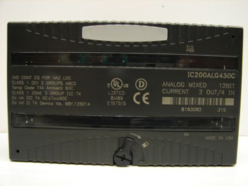
Section 6 – Analog Output Module (AO)

The Analog Output Module interfaces field analog output devices such as Control Valves, Display Meters etc. with the VersaMax PLC system.
-
Section 6.1 – LED Diagnostics

The Green FLD PWR LED indicates the presence of user-side power for the analog field side circuits.
The Green OK LED is ON when backplane power is present to the module.
This entry was posted on March 19th, 2015 and is filed under Support. Both comments and pings are currently closed.
PDF Supply sells used surplus products. PDF Supply is not an authorized distributor, affiliate, or representative for the brands we carry. Products sold by PDF Supply come with PDF Supply’s 1-year, 2-year, or 3-year warranty and do not come with the original manufacturer’s warranty. Designated trademarks, brand names and brands appearing herein are the property of their respective owners. This website is not sanctioned or approved by any manufacturer or tradename listed.
Rockwell Disclaimer: The product is used surplus. PDF Supply is not an authorized surplus dealer or affiliate for the Manufacturer of this product. The product may have older date codes or be an older series than that available direct from the factory or authorized dealers. Because PDF Supply is not an authorized distributor of this product, the Original Manufacturer’s warranty does not apply. While many Allen-Bradley PLC products will have firmware already installed, PDF Supply makes no representation as to whether a PLC product will or will not have firmware and, if it does have firmware, whether the firmware is the revision level that you need for your application. PDF Supply also makes no representations as to your ability or right to download or otherwise obtain firmware for the product from Rockwell, its distributors, or any other source. PDF Supply also makes no representations as to your right to install any such firmware on the product. PDF Supply will not obtain or supply firmware on your behalf. It is your obligation to comply with the terms of any End-User License Agreement or similar document related to obtaining or installing firmware.